One of the projects that I worked on previously required me to create a border effect that worked the same way the CSS border worked but for an SVG shape.
At first, I thought it would simply be a case of creating the first SVG shape, then a second scaled down shape, and using that to mask the first.
This worked well with regular shapes like a perfect square but does not work as expected with an irregular shape like rectangles.
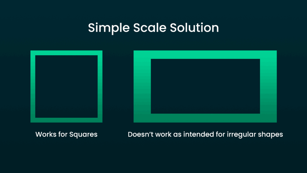
As you can see from the image above, some parts of the border appear thicker than others. This is because the border isn’t consistently offset from the shape’s outer edge. Ideally, the border should follow the contour of the shape at a constant distance from it, ensuring uniform thickness along the entire path.
So, what we need is a way to calculate a new inner SVG shape (to use as a mask for the outer shape), which follows these requirements.
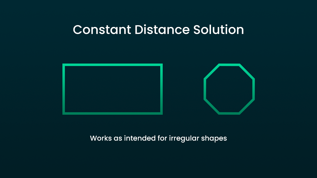
You will note in the image above, when the inner shape maintains a constant distance from the outer shape, the results are much better and follow the expected results of using a regular CSS border.
Let’s have a look at how this is done with code. You can get the code directly for this on Github.
Let’s start off with the below HTML code.
					<svg xmlns="http://www.w3.org/2000/svg" id="mainSVG" version="1.2" viewBox="0 0 2000 0">
    <path id="main" />
    <mask id="mainMask">
        <path id="mainBounds" />
        <path id="mainCutOff" />
    </mask>
</svg>
So, the main path will be the one which acts as the outermost path. Then the mask element contains two paths. The mainBounds path will have the exact same path as the main path, and the mainCutOff will use the new inner shape path that maintains a constant distance from the outer path.
To mask the main path, the mainBounds should be given a white colour and the mainCutOff should be given a black colour. With SVG masks, white parts are shown, and black parts are hidden.
Here’s the CSS to set the mask colours, and apply the mask to the outer path.
					#main{
  fill: #00d395;
  mask: url(#mainMask);
}

#mainCutOff{
  fill: black;
}

#mainBounds{
  fill: white;
}
Now it’s time for some JavaScript. This code will build paths and apply them to the SVG paths. I’ve included comments describing what’s happening at each step within the code.
					/*Class representing a 2D vector with commonly used vector operations
This solution requires a lot of vector operations and calculations
so this class is used to make the code more readable and maintainable
*/
class Vector2D {
  constructor(x, y) {
    this.x = x
    this.y = y
  }

  AddVector2D(v2) {
    return new Vector2D(this.x + v2.x, this.y + v2.y)
  }
  AddVector(x, y) {
    return new Vector2D(this.x + x, this.y + y)
  }
  SubtractVector(x, y) {
    return new Vector2D(this.x - x, this.y - y)
  }
  RotateClockWise90Degrees() {
    return new Vector2D(this.y * -1, this.x)
  }
  RotateAntiClockWise90Degrees() {
    return new Vector2D(this.y, this.x * -1)
  }
  GetMagnitude() {
    return Math.sqrt(Math.pow(this.x, 2) + Math.pow(this.y, 2))
  }
  Normalize() {
    return new Vector2D(this.x / this.GetMagnitude(), this.y / this.GetMagnitude())
  }
}

const borderWidth = 4; //Width of the desired border

//Add any number of vectors to create a path
const mainPathPoints = [
  new Vector2D(0, 0),
  new Vector2D(0, 1000),
  new Vector2D(800, 1000),
  new Vector2D(800, 0)
]

//Builds the SVG path and applies them to the SVG paths
function BuildSVG() {
  const pathMain = BuildPath(mainPathPoints)
  const pathMainMask = BuildPath(mainPathPoints, borderWidth)

  $('#goalMain').attr('d', pathMain)
  $('#goalMainBounds').attr('d', pathMain)
  $('#goalMainCutOff').attr('d', pathMainMask)
}

//Accepts a path of Vector2D's
function BuildPath(pathPoints, innerPadding = 0) {
  let path

  for (let i = 0; i < pathPoints.length; i++) {
    const currPoint = pathPoints[i]
    const nextPoint = GetNextPoint(pathPoints, i)
    const prevPoint = GetPreviousPoint(pathPoints, i)

    /*Difference between the current point and the previous point tells us how to go from
    the current point to the previous point. We then rotate this vector 90 degrees and then get
    the signed direction of the vector.
    */
    const firstPointDiff = currPoint.SubtractVector(prevPoint.x, prevPoint.y)
    let firstVecRotatedDir = firstPointDiff.RotateAntiClockWise90Degrees().Normalize()
    firstVecRotatedDir = new Vector2D(
      GetSignedDirection(firstVecRotatedDir.x),
      GetSignedDirection(firstVecRotatedDir.y)
    )

    /* Same as above but for the "next point" */
    const secondPointDiff = nextPoint.SubtractVector(currPoint.x, currPoint.y)
    let secondVecRotatedDir = secondPointDiff.RotateAntiClockWise90Degrees().Normalize()
    secondVecRotatedDir = new Vector2D(
      GetSignedDirection(secondVecRotatedDir.x),
      GetSignedDirection(secondVecRotatedDir.y)
    )

    /* (See Fig 1.0 for breakdown) Calculate the angle between the previous point, current point and a
    point that is 1 unit to the right of the current point. Then this is subtracted from 90
    to imagine a new triangle with a side opposite that angle of length innerPadding.

    Then with triggernometry we can calculate hypotenuse of this imagined triangle which informs us
    of the first Y poisition of the projected line.

    Then, using a mirrored triangle to the above imagined triangle, we can calculate the
    adjacent side of the triangle which informs us of the first X position of the projected line.

    The slope of the line between the previous point and the current point is also calculated.
    */
    const firstLineAngle =
      90 -
      CalculateAngleBetweenPoints(prevPoint, currPoint, new Vector2D(currPoint.x + 1, currPoint.y))
    let firstX = Math.cos(DegreesToRadians(firstLineAngle)) * innerPadding
    let firstY = Math.sin(DegreesToRadians(firstLineAngle)) * innerPadding
    const firstSlope = GetSlopeBetweenPoints(prevPoint, currPoint)

    /* Same as above but with the next point, current point and that is 1 unit to
    the right of the current point  */
    const secondLineAngle =
      90 -
      CalculateAngleBetweenPoints(nextPoint, currPoint, new Vector2D(currPoint.x + 1, currPoint.y))
    let secondX = Math.cos(DegreesToRadians(secondLineAngle)) * innerPadding
    let secondY = Math.sin(DegreesToRadians(secondLineAngle)) * innerPadding
    const secondSlope = GetSlopeBetweenPoints(nextPoint, currPoint)

    //Match the signs of the numbers
    firstX = MatchNumberSigns(firstX, firstVecRotatedDir.x)
    firstY = MatchNumberSigns(firstY, firstVecRotatedDir.y)
    secondX = MatchNumberSigns(secondX, secondVecRotatedDir.x)
    secondY = MatchNumberSigns(secondY, secondVecRotatedDir.y)

    /* This get's the actual positions of where we will project the lines by adding the firstX and
    firstY to the current point and the secondX and secondY to the next point

    The the X and Y values are multipled by the directional vector to ensure the lines are projected
    in the correct direction
    */
    const projectedCurrentPoint = new Vector2D(
      currPoint.x + firstX * Math.abs(firstVecRotatedDir.x),
      currPoint.y + firstY * Math.abs(firstVecRotatedDir.y)
    )
    const projectedNextPoint = new Vector2D(
      currPoint.x + secondX * Math.abs(secondVecRotatedDir.x),
      currPoint.y + secondY * Math.abs(secondVecRotatedDir.y)
    )

    /*
    Here using the projected points to get the Y-intercept of the projected lines
    We need these in order to solve the point of intersection for these lines
    */
    const fc = GetCoefficient(projectedCurrentPoint.x, projectedCurrentPoint.y, firstSlope)
    const sc = GetCoefficient(projectedNextPoint.x, projectedNextPoint.y, secondSlope)

    //Calculate the point of intersection between the two projected lines
    const intersection = GetLineIntersections(
      projectedCurrentPoint,
      firstSlope,
      projectedNextPoint,
      secondSlope,
      fc,
      sc
    )

    //With the intersection point we can add this to the path we're building
    if (!path) {
      path = `M${intersection.x} ${intersection.y}`
    } else {
      path += `L ${intersection.x} ${intersection.y}`;
    }
  }
  return path
}

function GetNextPoint(pathPoints, currentIndex) {
  if (currentIndex + 1 >= pathPoints.length) {
    return pathPoints[0]
  } else return pathPoints[currentIndex + 1]
}

function GetPreviousPoint(pathPoints, currentIndex) {
  if (currentIndex - 1 < 0) {
    return pathPoints[pathPoints.length - 1]
  } else return pathPoints[currentIndex - 1]
}

function GetSlopeBetweenPoints(p1, p2) {
  let yVal = p2.y - p1.y
  let xVal = p2.x - p1.x
  return yVal / xVal
}

//Get the translated coefficient of a line
function GetCoefficient(newX, newY, slope) {
  let coeff
  if (isFinite(slope)) {
    coeff = newY - newX * slope
  } else {
    coeff = newY - newX
  }
  return coeff
}

/* This is just an implementation of the point of intersection formula, which
give the vector position of an intersection between two lines */
function GetLineIntersections(
  firstPosition,
  firstSlope,
  secondPosition,
  secondSlope,
  firstCoefficient,
  secondCoefficient
) {
  let x, y

  if (!isFinite(firstSlope) && secondSlope == 0) {
    x = firstPosition.x
    y = secondCoefficient
  } else if (!isFinite(secondSlope) && firstSlope == 0) {
    x = secondPosition.x
    y = firstCoefficient
  } else if (!isFinite(firstSlope)) {
    x = (firstPosition.x + firstCoefficient - secondCoefficient) / secondSlope
    y = firstCoefficient
  } else if (!isFinite(secondSlope)) {
    x = (secondPosition.x + secondCoefficient - firstCoefficient) / firstSlope
    y = secondCoefficient
  } else {
    let slopeDifference = firstSlope - secondSlope
    x = (secondCoefficient - firstCoefficient) / slopeDifference
    y = firstSlope * x + firstCoefficient
  }
  return new Vector2D(x, y)
}

//Converts a number to a negative or positive number based on the target number sign
function MatchNumberSigns(numberToMatch, targetNumberSign) {
  if (targetNumberSign < 0) {
    return Math.abs(numberToMatch) * -1
  } else if (targetNumberSign > 0) {
    return Math.abs(numberToMatch)
  } else {
    return 0
  }
}

//Returns the sign of a number
function GetSignedDirection(directionValue) {
  if (directionValue < 0) {
    return -1
  } else if (directionValue > 0) {
    return 1
  } else {
    return 0
  }
}

//Calculate the direction between two points and normalize it
function GetVectorDirection(v1, v2) {
  let direction = new Vector2D(v2.x - v1.x, v2.y - v1.y)
  let magnitude = Math.sqrt(Math.pow(direction.x, 2) + Math.pow(direction.y, 2))
  let directonNormalized = new Vector2D(direction.x / magnitude, direction.y / magnitude)
  return directonNormalized
}

//Takes three vector positions and calculates the angle between them
function CalculateAngleBetweenPoints(p1, p2, p3) {
  let a = new Vector2D(p1.x - p2.x, p1.y - p2.y)
  let b = new Vector2D(p3.x - p2.x, p3.y - p2.y)
  let abProduct = a.x * b.x + a.y * b.y
  let magnitudeA = Math.sqrt(Math.pow(a.x, 2) + Math.pow(a.y, 2))
  let magnitudeB = Math.sqrt(Math.pow(b.x, 2) + Math.pow(b.y, 2))
  let radians = Math.acos(abProduct / (magnitudeA * magnitudeB))
  return RadiansToDegrees(radians)
}

//Converts radians to degrees
function RadiansToDegrees(radians) {
  let pi = Math.PI
  return radians * (180 / pi)
}

//Converts degrees to radians
function DegreesToRadians(degrees) {
  let pi = Math.PI
  return degrees * (pi / 180)
}
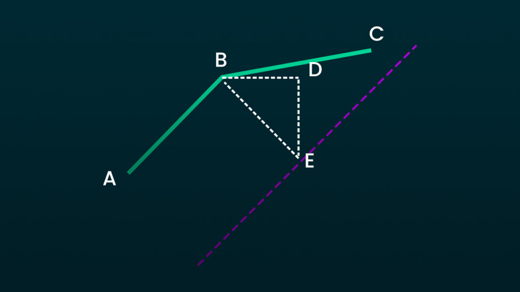
Fig 1.0 Breakdown
We need to calculate the position of point E along a parallel line to AB, where BE is the desired border width.
Steps:
Line AB and Parallel Line:
- BE represents the border width.
- The parallel line is offset from AB by this width.
Triangle BDE:
- BD is projected from B along the direction of AB.
- DE is perpendicular to BD, and the length of BE is the border width.
Solving for BD and DE:
Angle DBE:
Angle DBE = 90° – Angle ABDUse trigonometry to calculate the X and Y distances between B and E:
For DE (vertical displacement):
sin(θ) = DE / BE
So,DE = BE * sin(θ)For BD (horizontal displacement):
cos(θ) = BD / BE
So,BD = BE * cos(θ)
Result:
- Use BD (X displacement) and DE (Y displacement) to find point E on the parallel line.
Now we just repeat that process, instead imagining a parallel line of BC and calculating a point along it. Once again BE represents the border width.
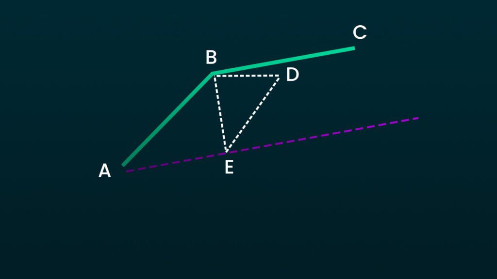
OK, so with that done, we now have two positions along the parallel lines of AB and BC. Now, since we already know their slopes, and a valid position along them, it’s a simple case of using the point of intersection formula.
This point of intersection represents a new path point for the innerPath. We simply repeat this process for all the vector positions in our path.